
How Does Lubricant Viscosity Affect a Filling Line Upgrade?
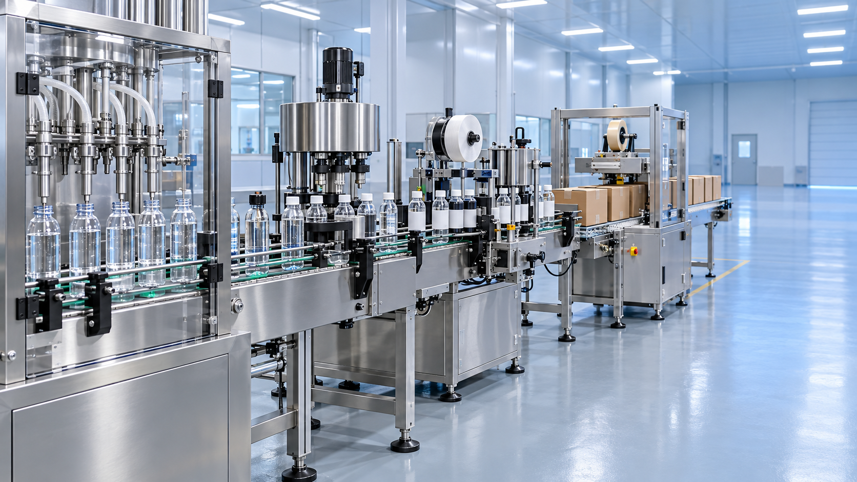
How Does Lubricant Viscosity Affect a Filling Line Upgrade?
Upgrading a lubricant filling line starts with understanding how viscosity affects flow, dosing accuracy, pump selection, and nozzle performance. A system that fills a light oil efficiently may struggle with a thicker lubricant, particularly during a cold start. Adding filling heads or increasing pump speed will not necessarily solve that problem; it may simply move the bottleneck upstream.
If you’re asking, “What should I send technical support when my lubricant filler stops working?” viscosity data, operating temperatures, alarm logs, and a short video of the fault are useful starting points. The same information also helps determine whether you need a targeted modification or a more substantial filling line upgrade.
The practical question is not whether a filler can handle “oil.” It is whether the complete system can handle your lubricant range, at actual operating temperatures, within the required filling tolerance and production schedule.
Start with viscosity at the filling temperature
A lubricant’s technical data sheet often lists kinematic viscosity at 40°C and 100°C. Those values help describe the product, but they do not directly establish how it will flow through a filling machine in an unheated production area. If the oil reaches the filler at a lower temperature, the equipment supplier needs viscosity information for that condition.
For pump and pressure-loss calculations, distinguish between kinematic viscosity, commonly expressed in centistokes, and dynamic viscosity, commonly expressed in centipoise. Converting between them requires density at the relevant temperature. Sending a viscosity number without its units and test temperature can lead to the wrong equipment assumptions.
Consider a line that runs acceptably after several hours but repeatedly underfills bottles at the beginning of the shift. Colder oil may be restricting the supply circuit or slowing chamber refill. Increasing the dosing setting could then cause overfilling once the product warms up. That pattern warrants temperature and inlet-flow checks before anyone changes the calibration.
Build the upgrade specification around the thickest expected product at the lowest normal operating temperature, while also checking the thinnest product at the warmest condition. Thick oil challenges delivery capacity; thin oil may expose leakage, pump slip, or poor nozzle shutoff. One successful test with a mid-range product does not cover both extremes.
Find the restriction before buying a larger pump
Viscous lubricants create more resistance through pipes, hoses, valves, filters, and manifolds. A filling machine may therefore be capable of the requested output while its supply arrangement is not. Long suction hoses, narrow fittings, low tank levels, and partially blocked filters can all reduce the oil available at the pump inlet.
A useful diagnostic distinction is whether every filling head slows down or only one head behaves differently. A line-wide problem points toward shared supply conditions, although controls can also be involved. An isolated problem makes a local valve, nozzle, seal, actuator, or branch restriction more likely. Neither observation proves the cause, but it gives troubleshooting a sensible direction.
Before specifying more pumping capacity, review the actual fluid path: tank outlet, suction-line diameter, hose length, elevation, filter pressure drop, and manifold arrangement. Simply driving a pump faster can worsen inlet starvation. Depending on the installation, a shorter inlet route or a less restrictive supply circuit may be more useful than a larger motor.
Filtration deserves particular attention during an upgrade. A filter selected for clean, warm oil may become a significant restriction with a colder or thicker grade. Where instrumentation permits, pressure measurements across the filter help distinguish restriction from a pump fault. Do not remove required filtration merely to recover speed; review filter area, rating, and contamination-control requirements together.
Pump choice and dosing method are separate decisions
Positive-displacement pumps are often considered for lubricant service because they move a defined volume per cycle or revolution. Gear, screw, and other designs have different limits for viscosity, speed, inlet conditions, wear, and product compatibility. Suitability still needs confirmation against the pump manufacturer’s operating envelope.
A critical detail is pressure protection. A positive-displacement pump can generate excessive pressure against a closed discharge. An upgrade must retain appropriately engineered relief or bypass protection and pressure-rated components. Raising a pressure limit to stop nuisance trips is not a substitute for finding the restriction.
The pump supplying the filler does not necessarily determine how each bottle is measured. The dosing method needs its own review:
- Timed filling: Dispensed quantity depends on flow remaining sufficiently stable. Temperature, pressure, and viscosity changes can alter the result even when valve-open time stays unchanged.
- Piston filling: A defined chamber displacement can suit viscous products, but the chamber must refill completely. Restricted intake or trapped air can undermine repeatability.
- Flow-meter filling: Performance depends on meter technology, operating range, installation, and entrained air. A meter suitable for one liquid should not be assumed suitable for every lubricant.
- Net-weight filling: Measuring mass reduces reliance on a fixed volume-to-mass conversion, but accurate cutoff still depends on stable weighing, controlled flow, and predictable material remaining in transit.
Define acceptance in the same terms used for production release. If bottles are filled volumetrically but checked by weight, density and temperature belong in the evaluation. Otherwise, an apparent dosing error may partly reflect a conversion assumption.
Nozzle cutoff can limit speed more than bulk flow
A thicker lubricant may leave a tail or string after the valve closes. A thinner grade may drip through a worn seat or unsuitable seal. Both can contaminate bottle necks, affect closures, and create housekeeping problems, but they do not call for the same correction.
Increasing nozzle diameter can reduce flow resistance, yet the bottle opening, neck clearance, and final cutoff behavior still matter. A larger nozzle is not automatically a cleaner nozzle. Evaluate the shutoff position, internal hold-up volume, filling height, and whether controlled suck-back is appropriate. Excessive suck-back can introduce air or disturb the next dose.
Bottom-up filling or a slower initial flow may help manage splashing and air entrainment for some products and containers. These features should be tested rather than added by default. Lubricant additives, incoming aeration, and container geometry can change the result.
Time the whole cycle: bottle positioning, nozzle movement, filling, settling, cutoff, and indexing. If the machine must wait for a lubricant tail to break before releasing the bottle, increasing pump capacity alone will not deliver the expected throughput.
What should I send technical support when my lubricant filler stops working?
Send evidence that allows support to distinguish a mechanical stop, a control interlock, and a product-flow problem. “The filler won’t run” is less useful than “the conveyor indexes normally, but filling does not start after the bottle-present signal.” Capture the original condition before repeated resets obscure the sequence.
- Equipment identification: Machine model, serial number, installed options, and software version if readily available.
- Product information: Lubricant name or grade, technical data sheet, viscosity with units and test temperature, and actual product temperature near the filler. Include the safety data sheet when product handling or compatibility is relevant.
- Fault sequence: Exact alarm text or code, timestamp, operating step, and whether the problem followed a grade change, cleaning, maintenance, or parameter adjustment.
- Operating conditions: Selected recipe, target quantity, current speed, tank level, displayed pressures, and available air-supply readings.
- Visible symptoms: Whether the pump runs, whether all heads are affected, and whether there is leakage, foaming, unusual noise, or inconsistent fill quantity.
- Supporting records: A short video showing the HMI and affected area, alarm-history screenshots, and recent fill-check results labeled by head where possible.
Record only from a safe position. Do not bypass guards, defeat interlocks, loosen pressurized connections, or reach into moving equipment to obtain footage. Maintenance inspections require the site’s isolation procedures and trained personnel. If temperature is unavailable, report that gap rather than estimating it.
Upgrade the line around the filler—not just the filler itself
A faster lubricant filler changes the demands on conveyors, bottle positioning, capping, and downstream packing. Oil on a bottle neck can compromise closure application; oil on the exterior can cause handling problems. Check conveyor stability, capper capacity, and carton-sealing flow at the proposed output rather than relying on individual machine nameplate speeds.
Suppliers offering filling machines alongside rinsing, drying, conveying, capping, filtering, and carton-sealing equipment can assess these interfaces together. However, experience filling edible oil, beverages, or detergent does not by itself validate a lubricant application. Seal compatibility, contamination control, product viscosity, and cleaning requirements need separate confirmation. Bottle washing or rinsing should only be included when the process requires it, with residual moisture controlled appropriately.
For a smaller operation, a targeted retrofit may be the better choice: revised inlet plumbing, suitable nozzles, improved temperature monitoring, or additional recipe control. OEM integration or a tailored line becomes more relevant when the existing controls, mechanics, and downstream equipment cannot support the required product range. Ask the supplier to identify what can safely remain, not merely what can be replaced.
Make the trial reflect your difficult production conditions
Before approving the upgrade, agree on trials using representative lubricants and containers. Include cold starts, steady running, low supply-tank level, grade changes, and stop-and-restart behavior where these occur in normal production. Check every filling head, not only the average output.
Acceptance should cover fill tolerance, sustained throughput, neck cleanliness, drips, alarms, and changeover losses. Any heating proposal also needs review against the lubricant supplier’s guidance, material compatibility, and site safety requirements. Heating may improve flow, but it should not conceal undersized pipework or inadequate inlet conditions.
The most useful next step is to document your product-temperature range and current failure pattern, then request a clearly defined trial. A filling line upgrade is justified when it handles the difficult operating conditions predictably—not just when it runs faster with warm oil during a demonstration.
Thank you very much for writing to us. Please leave your message and contact information, we will reply to you within 24 hours.