
Why Does Lubricant Fill Weight Drift at Only One Filling Nozzle?
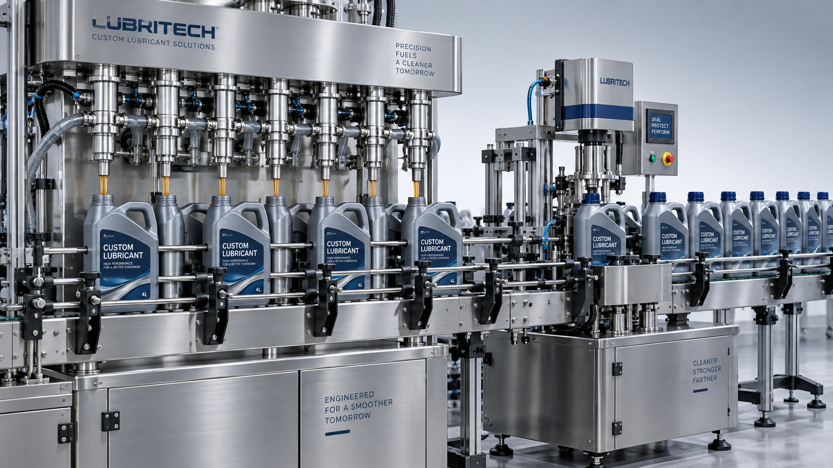
When lubricant fill weight drifts at only one nozzle, start with the components and signals unique to that station. A sticking shutoff valve, trapped air, restricted hose, leaking piston seal, or unstable load cell can change one fill while neighboring stations remain consistent. Recalibrating the entire machine before isolating the fault risks shifting stations that already fill correctly.
Repeat filling performance verification after installation, but match the retest scope to the evidence. An isolated defect with a confirmed local cause usually calls for focused verification plus comparison with unaffected stations. Changes to shared controls, product supply, utilities, or machine mounting justify broader testing. Any agreed site acceptance procedure still determines the required formal scope.
Is the weight actually drifting, or is one station consistently wrong?
A nozzle that stays below target has a different problem from one whose average gradually moves during production. A stable offset points toward station settings, calibration, or repeatable cutoff behavior. Progressive drift suggests a changing condition: lubricant temperature, air accumulation, valve heating, seal leakage, or pressure loss as a restriction develops. Widely scattered results indicate poor repeatability and need a different investigation.
Record consecutive net weights by nozzle, keeping their production order. Include startup, steady running, and restart after a normal pause. Calculate each station’s average and spread separately; a machine-wide average can hide an underfilling station when another fills heavy. Preserve the sequence because an acceptable average can conceal a steady decline.
Confirm the measurement before opening the filling circuit. Establish actual container tare rather than relying on a nominal bottle weight. Use a suitable independent scale with verified performance, and weigh at a consistent point after filling. Oil on the bottle exterior, delayed dripping, or variable container tare can create apparent nozzle variation.
What does the filling method reveal about the fault?
The same weight pattern has different explanations on timed, volumetric, and gravimetric equipment. Identify what actually ends the dose before adjusting a setting.
Timed and volumetric filling
On a timed filler, delivered volume depends on flow during the valve-open period. A partially blocked branch, reduced valve opening, or local pressure loss lowers that station’s output even when its programmed duration is unchanged. Extending fill time can conceal the restriction until operating conditions change again.
For piston or other positive-displacement dosing, investigate incomplete chamber filling, seal bypass, check-valve leakage, and air entering the metering volume. A commanded stroke does not prove that the same liquid volume reaches the bottle. If output falls as speed increases, the chamber may have insufficient time to refill through a restricted inlet.
Temperature also affects interpretation. For a fixed delivered volume, lubricant mass changes with density. Temperature affects viscosity as well, changing flow resistance and refill behavior. A common temperature shift should prompt comparison across all nozzles; a single marginal branch can respond more strongly than the others.
Gravimetric filling
A weight-controlled station should compensate for flow changes while the measured load remains reliable and the control has enough adjustment range. Investigate tare stability, cutoff timing, material delivered after valve closure, and mechanical contact with the weighing assembly.
Compare the station’s displayed net weight with an independent measurement of the same bottle. Agreement directs attention toward dosing behavior or control settings. A changing disagreement points toward the measurement chain, including load-cell mounting, cable faults, electrical noise, or forces transmitted through guides and hoses.
Which local faults produce recognizable patterns?
These patterns guide investigation; none identifies a failed part on its own. A sticky valve, for example, can restrict opening and cause low fills, then close slowly and cause heavy fills on another cycle.
Where should the physical inspection begin?
Trace the affected station from its supply branch to the nozzle tip. Compare hose routing, internal diameter, fittings, valve orientation, and nozzle height with a stable neighboring station. A hose kink introduced during installation or a gasket protruding into a fitting can create enough resistance to affect viscous lubricant without producing an obvious external symptom.
Inspect the local actuator supply as well. On a pneumatically operated valve, a restricted air tube, sticking solenoid, or poor exhaust path can delay movement. Pressure measured at the main regulator does not establish that adequate pressure reaches the actuator during cycling. Compare commanded valve timing with actual movement where the equipment permits safe observation.
Before opening product connections, isolate motion and release stored pressure according to the machine procedure. Inspect valve seats, seals, and nozzle passages for damage or contamination. Confirm replacement seal compatibility with the lubricant and operating temperature; a dimensionally similar seal can behave differently when exposed to the product.
Air deserves particular attention after installation or maintenance. A high point in an individual branch can retain a pocket even after the main manifold has been primed. Suction-side connections can draw air inward without leaking oil outward. Use the approved priming or venting procedure and determine whether the fault returns after a pause.
Could installation disturb only one weighing station?
Yes. One load-cell assembly can experience forces that do not affect the others. A bottle guide touching the weighing platform, a tight hose pulling on a mounted component, or an incorrectly seated platform can change the indicated weight. The problem may appear only when the conveyor starts or the bottle moves into position.
Begin with an empty platform and observe zero stability. Then apply suitable verified test weights using the manufacturer’s procedure. Look for repeatability, return to zero, and sensitivity to load position where applicable. A successful zero adjustment alone does not establish correct performance under load.
Compare readings with nearby equipment stopped and running. Conveyor vibration and electrical interference can produce similar-looking instability, but they require different corrections. Inspect cable routing, connectors, shielding, and grounding against the installation documentation. Increasing signal filtering without investigating the cause can delay the controller’s response to incoming lubricant.
Mechanical weighing faults must be corrected before calibration. Calibrating around a guide touching the platform creates an adjustment that becomes wrong as soon as the contact changes.
How can the fault be isolated without losing the evidence?
Keep the product, target weight, container, and operating speed unchanged during the first comparisons. Record existing settings before adjusting anything. Altering fill time, cutoff compensation, and supply pressure together can restore an acceptable average while leaving the underlying defect unidentified.
- Collect a baseline from the affected station and at least one stable station under the same conditions. Retain individual weights and their sequence.
- Compare a controlled reduced-speed run with normal production speed. Improvement at reduced speed supports investigation of refill time, flow restriction, or valve response, although it does not establish which component is responsible.
- If the design and maintenance procedure allow it, exchange one identical serviceable component between stations, such as a nozzle tip or valve assembly. Maintain cleanliness and record the component locations. A fault that follows the component provides stronger evidence than repeated setting changes.
- Repeat the original operating condition after the correction, including the pause or speed change that previously exposed the fault.
If the fault stays at the same station after a permitted component exchange, investigate the branch piping, actuator supply, wiring, and station control. Inspect before exchanging parts where damage or contamination could be transferred to a good station.
Should we repeat the lubricant filling acceptance test after installation?
Yes, installed filling performance needs verification under the agreed site conditions. Factory results establish performance in the factory test arrangement. Installation introduces different hose routes, utility connections, conveyor forces, product supply conditions, and sometimes different lubricant temperatures. Those differences explain why satisfactory factory results do not close an installation-related investigation.
The extent of a repeat test should follow the change and the original acceptance agreement. Replacing a defective tip or correcting an isolated guide contact generally supports focused testing of the repaired station, with unaffected stations serving as controls. Confirm the station across relevant operating conditions, including restart behavior, rather than accepting a few favorable bottles.
A broader retest is warranted when the correction changes shared conditions: manifold pressure, pump control, common dosing software, recipe parameters used by every station, or machine support and leveling. Broaden the scope as well when the evidence no longer supports an isolated fault or several stations show a common trend.
Formal acceptance requirements take precedence over an informal decision to narrow testing. Where a documented protocol requires all stations to be tested after a particular intervention, complete that scope even if troubleshooting identified one defective component.
What evidence is enough to release the corrected station?
Use the agreed fill-weight limits and sampling plan. Assess both average error and individual variation; a correct average does not establish that individual containers meet the requirement. Keep results separated by nozzle, and compare the repaired station with its baseline and neighboring stations.
Test with the intended lubricant and representative containers at relevant production conditions. A substitute liquid with different viscosity or air-release behavior can miss the original problem. Include normal warm-up, steady operation, and restart conditions when they affected the fault. Record product temperature, speed, supply conditions, and settings so later comparisons have a usable reference.
The release record should connect the observed pattern to the identified cause, the correction, and the verification results. If acceptable weights depend on repeatedly increasing compensation, the cause remains unresolved and the station needs further investigation.
Thank you very much for writing to us. Please leave your message and contact information, we will reply to you within 24 hours.